

Circuit Analysis involves figuring out the electrical potential differences and flows through particular elements in a network by employing mathematical representations and basic physical principles. This field requires utilizing Kirchhoff’s rules along with diverse circuit principles to ascertain the unnamed quantities within systems that are straightforward, two-way, and either non-power-generating or power-consuming.
Core Elements of Circuit Analysis
Circuit Analysis begins with identifying the nature of components within a network. You must distinguish between active elements like voltage sources and passive elements like resistors or capacitors. Active elements supply energy to the system while passive elements absorb or store it. This distinction is vital for setting up nodal or mesh equations correctly.
The RPSC Assistant Professor Physics Syllabus requires a deep understanding of how these elements interact under different conditions. You will encounter four terminal networks where input and output behavior is defined by Z, Y, and h parameters. These parameters allow you to treat a complex circuit as a black box with specific transfer characteristics.
The study of Mean and rms values in AC circuits provides the foundation for power calculations in Circuit Analysis. You use root mean square values to represent the effective DC equivalent of an alternating current. This knowledge extends to analyzing LR, CR, and LCR circuits where phase relationships between voltage and current determine the overall impedance and resonance behavior in Circuit Analysis.
Kirchhoff’s Laws and Network Applications
Kirchhoff’s Laws represent the most fundamental tools for any Circuit Analysis task. These laws consist of Kirchhoff’s Current Law (KCL) and Kirchhoff’s Voltage Law (KVL). KCL states that the algebraic sum of currents entering a junction is zero. This is a direct consequence of the principle of conservation of electric charge.
∑I = 0
Kirchhoff’s Voltage Law centers on energy preservation inside an unbroken circuit. It asserts that the total of all EMFs and potential drops encircling any complete loop within a circuit totals zero. You apply these laws to transform a physical circuit diagram into a set of simultaneous linear equations in Circuit Analysis.
∑V = 0
When you prepare for the RPSC Assistant Professor Physics Syllabus, you must apply Kirchhoff’s Laws to complex multi-loop systems. These laws work for both DC and AC circuits provided you use phasor notation for alternating quantities. Understanding these laws is a prerequisite for mastering more advanced theorems that simplify network reduction.
Thevenin’s and Norton’s Theorem for Network Simplification
Thevenin’s and Norton’s Theorem provide methods to simplify any linear bilateral network into a single source and a single impedance. As per Circuit Analysis, Thevenin’s Theorem replaces a complex network with an equivalent voltage source (Vth) in series with an internal resistance (Rth). This simplifies the calculation of current through a variable load resistor.
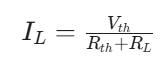
Norton’s Theorem offers a dual perspective by replacing the same network with an equivalent current source (In) in parallel with a Norton resistance (Rn). The relationship between these two theorems is defined by source transformation. Rth and Rn are always identical in value for the same network.
Applying Thevenin’s and Norton’s Theorems lets you concentrate on a particular branch without having to recalculate the whole circuit when the connected load varies. These principles are vital for tackling challenges outlined in the RPSC Assistant Professor Physics Syllabus. They lessen the calculation effort in substantial networks by separating the circuit section being examined.
[Image of Thevenin and Norton equivalent circuit transformation]
Maximum Power Transfer Theorem
The Maximum Power Transfer Theorem establishes the circumstances under which a source provides peak power to a connected load. In the context of a DC circuit, this peak power transfer is achieved when the load resistance (RL) matches the source’s internal resistance (Rs). For AC circuits, the required condition is that the load impedance must be precisely the complex conjugate of the source impedance.
RL = Rs
This theorem is a fundamental principle in Circuit Analysis for communication systems and power electronics. Although the efficiency reaches only 50% at the point of peak power transfer, this scenario is favored in signal processing where signal magnitude takes precedence over energy saving. You must calculate the internal resistance using Thevenin’s techniques before applying this theorem.
The RPSC Assistant Professor Physics Syllabus highlights the mathematical derivation of this principle. To demonstrate the necessary condition, you differentiate the power formula relative to RL and equate it to zero. Grasping the balance between performance and energy transfer is a vital realization for sophisticated physics uses.
Superposition Theorem for Multi-Source Networks
The Superposition Theorem states that in a linear network containing multiple sources, the response in any branch is the algebraic sum of the responses caused by each source acting alone. You deactivate all other independent sources while calculating the effect of one specific source in Circuit Analysis. Voltage sources are replaced by short circuits and current sources by open circuits.
This theorem simplifies Circuit Analysis by breaking one complex problem into several simpler ones. It only applies to linear parameters like voltage and current. You cannot use the Superposition Theorem to calculate power directly because power has a non-linear (square) relationship with current and voltage.
In the context of the RPSC Assistant Professor Physics Syllabus, the Superposition Theorem is frequently tested through bridge circuits or multi-mesh networks. You must ensure that dependent sources remain active during the analysis. This theorem provides a systematic way to handle circuits where different frequencies or types of sources coexist.
Reciprocity Theorem and Symmetrical Networks
The Reciprocity Theorem holds true for linear, two-way, single-source circuits. It asserts that if a voltage source in one part generates a specific current in another part, that identical voltage source moved to the second part will yield the very same current in the original part. This principle underscores the built-in symmetry often present in electrical setups within Circuit Analysis.
V1/I2 = V2/I1
This principle is useful when analyzing T and PI Network structures in Circuit Analysis. These networks are common in filter design and attenuators. You use the Reciprocity Theorem to verify the consistency of your measurements or to simplify the calculation of transfer functions in bidirectional communication lines.
The RPSC Assistant Professor Physics Syllabus includes this theorem to build a foundation for electromagnetic theory. While Reciprocity Theorem is highly reliable in passive networks, it fails in circuits containing non-bilateral elements like diodes or transistors. Recognizing these limits is a sign of advanced technical proficiency.
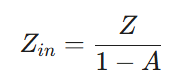
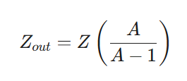
Miller Theorem and Impedance Transformation
Miller Theorem offers a potent method for examining feedback within high-gain amplifiers. It asserts that an impedance linking the amplifier’s input and output may be substituted with two distinct impedances: one positioned at the input and another at the output. This transformation depends on the voltage gain (A) of the circuit.
The equivalent impedance seen at the input is:
The equivalent impedance seen at the output is:
In Circuit Analysis, the Miller Theorem often explains the “Miller Effect” where input capacitance is effectively multiplied by the gain. This significantly impacts the frequency response of LR, CR and LCR circuits. You use this theorem to simplify feedback loops into parallel combinations that are easier to solve.
The RPSC Assistant Professor Physics Syllabus encompasses the Miller Theorem to connect fundamental circuit principles with active electronic components. It enables the modeling of intricate relationships consistently with Kirchhoff’s Laws, while incorporating active amplification. Proficiency in this theorem is essential for developing reliable high-frequency setups.
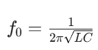
Resonance and Quality Factor in LCR Circuits
Resonance occurs in LCR circuits when the inductive reactance and capacitive reactance are equal in magnitude but opposite in phase. In series resonance, the impedance is at its minimum and current is at its maximum. In parallel resonance, the impedance reaches its peak and current is minimized.
The Quality factor (Q) measures the sharpness of the resonance peak. A high Quality factor indicates a narrow bandwidth and lower energy loss. This is a critical parameter in the RPSC Assistant Professor Physics Syllabus for understanding tuning and selectivity in radio frequency applications.
Resonance analysis requires an understanding of Mean and rms values in AC circuits to evaluate power dissipation in Circuit Analysis. You must be able to calculate the bandwidth and the half-power frequencies. These concepts are used in the Principal of transformer design to ensure efficient energy transfer at specific operating frequencies.
Essential Formulas for Circuit Analysis
| Theorem / Concept | Primary Mathematical Expression | Application Focus |
|---|---|---|
| Kirchhoff’s Voltage Law | ∑V = 0 | Loop analysis and energy conservation |
| Kirchhoff’s Current Law | ∑I = 0 | Junction analysis and charge conservation |
| Thevenin Equivalent | Vth = Voc; Rth = Voc/Isc | Load current calculation |
| Maximum Power Transfer | RL = Rth | Impedance matching for power |
| Miller Effect Input | Cin = C(1 + A) | Frequency response in amplifiers |
| Resonance Frequency | f = 1/(2π√LC) | Filter and tuning circuits |
| Quality Factor | Q = ωL/R | Selectivity and bandwidth |
Limitations and Practical Constraints
Established principles of Circuit Analysis frequently presume perfect scenarios absent in practical settings. A frequent error involves using the Superposition Theorem for power assessments without noting power’s quadratic nature. If current is doubled, power increases fourfold; it doesn’t merely double. This non-linear characteristic mandates determining the overall voltage or current beforehand, prior to calculating power.
Regarding Circuit Analysis, an additional constraint arises from the Maximum Power Transfer Theorem. Although this theorem delivers peak power to the load, it simultaneously yields poor efficiency. In large-scale power distribution, engineers avoid this condition because it would cause massive heat dissipation within the source itself. You must distinguish between signal-level applications where power transfer is the goal and power-system applications where efficiency is the priority.
T and PI Network models also face challenges at extremely high frequencies. Parasitic capacitance and inductance, which are usually ignored in the RPSC Assistant Professor Physics Syllabus at introductory levels, become dominant. These elements might cause a feedback network to act asymmetrically or shift the tuning point of an LCR system. Consistently confirm whether your component representations hold true at your working frequency.
Real-World Application: Audio System Design
Using the Maximum Power Transfer Theorem ensures the amplifier drives the speakers effectively. The Quality factor of the crossover filters must be carefully managed. If the Q is too high, the audio will have unnatural peaks at the crossover frequency. If it is too low, the transition between speakers will be muddy and poorly defined.
In Circuit Analysis, engineers employ Thevenin’s and Norton’s Theorems to represent the amplifier’s output stage. This approach enables them to forecast the crossover’s behavior when connected to varied speaker impedances. This real-world utilization effectively integrates nearly all components of the RPSC Assistant Professor Physics Syllabus into one working apparatus.
Final Thoughts
Grasping the core tenets of Circuit Analysis extends beyond simply meeting examination benchmarks; it represents the essential dialect of electrical engineering and deeper physics. By thoroughly understanding the flow of energy within both passive and active circuits, you acquire the capacity to forecast system responses and diagnose intricate hardware issues with calculated accuracy. Regularly employing these principles across varied contexts is crucial for developing the necessary instinct for solving advanced challenges in academic research and professional settings. VedPrep offers a complete collection of tools and professional mentorship to enable you to tackle these technical ideas assuredly.
To know more in detail, watch our Youtube video:
Frequently Asked Questions (FAQs)
How does Kirchhoff’s Voltage Law apply to network loops?
Kirchhoff’s Voltage Law (KVL) states that the algebraic sum of all electric potential differences around any closed loop equals zero. You use KVL to account for energy conservation within a circuit. This law ensures that the energy supplied by sources matches the energy dropped across passive components.
What is the significance of Kirchhoff’s Current Law at junctions?
Kirchhoff’s Current Law (KCL) dictates that the total current entering a junction must exactly equal the total current leaving it. This principle relies on the conservation of electric charge. You apply KCL to nodal analysis to solve for unknown node voltages in complex multi-branch networks.
Why is the RPSC Assistant Professor Physics Syllabus focused on circuit theorems?
The RPSC Assistant Professor Physics Syllabus emphasizes theorems because they provide systematic shortcuts for complex calculations. Mastery of these theorems demonstrates a candidate's ability to simplify intricate physical systems into manageable linear equations. This proficiency is essential for advanced academic instruction and research.
What distinguishes active elements from passive elements?
Active elements like voltage and current sources have the capacity to deliver net energy to the circuit for an indefinite period. Passive elements such as resistors, capacitors, and inductors either dissipate energy or store it in electric or magnetic fields. You must correctly identify these to set up equations.
How do you calculate a Thevenin equivalent voltage?
To find the Thevenin equivalent voltage, you must first remove the load resistor to create an open circuit. You then calculate the voltage across these open terminals using standard nodal or mesh analysis. This voltage represents the equivalent source value for the entire linear network.
When should you use the Superposition Theorem?
You should use the Superposition Theorem when a linear network contains multiple independent sources. By calculating the contribution of each source individually while short-circuiting other voltage sources and opening other current sources, you simplify the math. You then sum these individual contributions for the final result.
How do you determine the Norton equivalent current?
You determine the Norton equivalent current by placing a short circuit across the output terminals of a network. The current flowing through this short is the Norton current. This value, paired with the equivalent resistance in parallel, provides a complete model of the original network behavior.
How do you apply the Miller Theorem to feedback loops?
You apply the Miller Theorem by splitting a floating impedance that connects the input and output of an amplifier into two grounded impedances. You use the circuit gain to calculate the new input and output values. This transformation allows you to analyze feedback systems as simple parallel circuits.
Why does the Superposition Theorem fail for power calculations?
The Superposition Theorem fails for power because power is a non-linear function proportional to the square of current or voltage. Summing individual power values leads to incorrect results. You must calculate the total current or voltage first and then perform the power calculation using the combined value.
What causes a circuit to fail the Reciprocity Theorem?
A circuit fails the Reciprocity Theorem if it contains non-linear or unilateral components like diodes, transistors, or dependent sources. These elements do not maintain the same impedance characteristics when the direction of energy flow changes. Only passive, bilateral networks strictly adhere to this theorem.
How do four terminal network parameters improve Circuit Analysis?
Four terminal network parameters like Z, Y, and h allow you to describe a complex circuit using only input and output relationships. You do not need to know the internal components to predict how the network interacts with other stages. This abstraction is vital for modular system design.
What role does the complex conjugate play in AC power transfer?
In AC systems, the Maximum Power Transfer Theorem requires the load impedance to be the complex conjugate of the source impedance. This ensures that the inductive reactance of the source cancels out the capacitive reactance of the load. Only the real resistive parts remain for maximum energy delivery.
What happens to Miller capacitance at very high frequencies?
At extremely high frequencies, the Miller capacitance can dominate the input impedance, creating a low-pass filter effect that limits bandwidth. This effectively reduces the gain of the amplifier stage. You must account for this parasitic behavior when designing high-speed communication circuits or wideband sensors.
How do T and PI networks relate to filter design?
T and PI networks serve as the building blocks for ladder filters and attenuators. By choosing specific reactive components, you can create low-pass, high-pass, or band-pass characteristics. These symmetrical structures allow for easy impedance matching and predictable phase shifts across the RPSC syllabus topics.